TASverterGUI
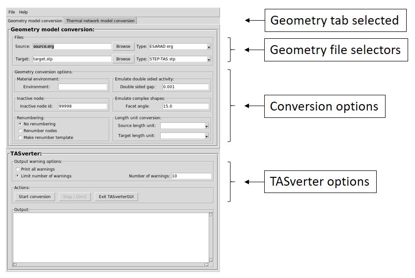
The TASverter graphical user interface is started by running TASverter with the –gui flag. The TASverterGUI main window should then appear with the Geometry model conversion tab selected:
The TASverterGUI is a simple graphical user interface layer that calls the main TASverter tool. The GUI provides access to the full capabilities of TASverter in an intuitive way so that the user can easily experiment and learn about TASverter and its options. The information that the user enters in the TASverterGUI input fields is converted into an appropriate TASverter command line that is then run using the appropriate underlying operating system. The output generated by TASverter is captured and displayed in the text area of the TASverterGUI.
The TASverterGUI consists of one main window containing all the menus, edit boxes, buttons, etc. needed to specify the parameters and options to be passed to TASverter. These controls are grouped in the following way:
The Geometry model conversion tab
These controls allow the user to choose the source and destination file names and types for the conversion to be performed by TASverter.
Source Model File input field:
allows the user to enter the full path of the file to be converted.
Source Browse button:
pops up a file chooser dialog so that the user can navigate the file system to locate the file to be converted.
Source Model Type menu button:
allows the user to choose the format of the input file to convert from a menu of formats supported by TASverter.
Target Model File input field:
allows the user to enter the full path of the file to which the converted model will be written.
Target Browse button:
pops up a file chooser dialog so that the user can navigate the file system to specify the output file.
Target Model Type menu button:
allows the user to choose the format of the output file from a menu of formats supported by TASverter.
The Geometry model settings area
These controls allow the user to specify particular options to be passed to TASverter.
Material Environment:
sets the value for the –material_environment parameter that may be passed to TASverter. This option allows the selection of the preferred material environment in the case that the source model contains more than one material environment and the format of the destination does not support multiple material environments.
Inactive Node:
sets the value for the –inactive_node parameter that may be passed to TASverter. The value in the input field is used as the thermal node number to be assigned to double-sided surfaces where both faces are inactive.
This option is useful for those analysis tools which apply a special meaning to double-sided surfaces where both faces are inactive. Note that the inactive side of a double-sided surface where only one face is inactive is handled automatically by the analysis tools themselves.
Renumbering:
activates the –renumber and –make_renumber_template parameters that may be passed to TASverter. By default, these options are not activated.
No Renumbering:
if this option is set, TASverter does not renumber thermal nodes.
Renumber Nodes:
if this option is set, TASverter attempts to renumber thermal nodes using the renumbering specified in a file called “SOURCE_FILE.renumber”. This file can be created using the Make Renumber Template option; editing the generated file to specify the actual nodes that the user wants to renumber; and renaming this file to “SOURCE_FILE.renumber”.
Make Renumber Template:
forces TASverter to generate a template for the renumbering input file. TASverter will also generate a sorted list of thermal node numbers from which the free node number ranges can be identified. Note that this option may be automatically activated by TASverter when:
The maximum node number in the original model exceeds the supported maximum node number allowed in the destination tool format. In this case, the user is required to specify a renumbering such that the maximum node number is not exceeded.
The original model contains a thermal network model with submodels and the destination tool format does not support submodels. In this case, the user is required to specify a renumbering such that thermal nodes with the same node numbers but in different submodels are mapped to different node numbers.
Emulating Double Side Activity:
set the value for the –double_sided_gap parameter that may be passed to TASverter.
This option is useful as a work around solution for those analysis tools which do not allow different thermal node numbers for the two sides of a double-sided surface where both surfaces are active. For those particular tools, TASverter generates two surfaces with a single active face each separated by the given gap size. The two separate single-sided surfaces can then have different thermal node numbers.
See also the Thermica3 SYSBAS geometry conversion notes.
Emulation of Complex Shapes:
set the value for the –facet_angle parameter that may be passed to TASverter.
This option specifies the angle, in degrees, to be spanned by conical facets when approximating complex shapes. This is used for the TRASYS spheroid, ogive and toroid.
Length Unit Conversion:
specify the length units to be used for the source and destination models. These buttons correspond to the –source_length_unit and –destination_length_unit options of TASverter.
Source Length Unit:
specify the length units used in the source model. If no unit is specified in the source model itself, the source length unit defaults to “metre”.
Destination Length Unit:
specify the length units used in the destination model. If no unit is specified, or used implicitly by the destination model format, the destination length unit defaults to “metre”.
These menu buttons allow the user to choose one of the supported length units. The accepted units are: m (metre), cm (centimetre), mm (millimetre), in (inch) and ft (foot).
The Network model conversion tab
These controls allow the user to choose the source and destination file names and types for the conversion to be performed by TASverter. They are very similar to the Geometry model conversion tab above, but limit the choice of file type to those relevant for TMM conversion.
There is no corresponding Network model settings area.
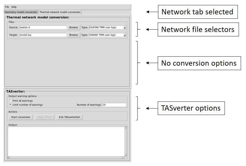
The TASverter area
The Output warning options
Print all warnings:
corresponds to the TASverter –all_warnings option.
Limit number of warnings:
corresponds to the TASverter –max_warnings_number option.
Number of warnings:
the number of warnings of the same type that are reported immediately to the user will be limited to the value in the “Number of Warnings” input field.
Note that although these options affect the warnings that are reported immediately to the user in the GUI, TASverter always records all warnings in the log file.
The Output message area
The Message Area displays all of the text output generated while running TASverter from the GUI. The TASverterGUI does not perform any further analysis of the output, so the user must check the contents of the Message Area to determine whether the TASverter conversion was successful.
Note that the information printed in the Message Area can also be found in the log files generated by TASverter.
The Dialogs
The TASverterGUI only uses dialogs when browsing for file locations, and when reporting input error messages.
The old Preferences menu and dialog no longer exist because the new TASverter executable effectively contains all relevant files.